
Valve Box Lid Mount
The device mounts into the device mounting dock that is installed to the underside of a standard irrigation valve box lid, hidden inside the box and accessible from the surface without digging. The same hardware kit and process applies to both Water Buddi and Drip Defender.
Estimated time: 20 minutes
Tools required: drill with 1/8" bit, included 2.0 mm and 2.5 mm hex keys
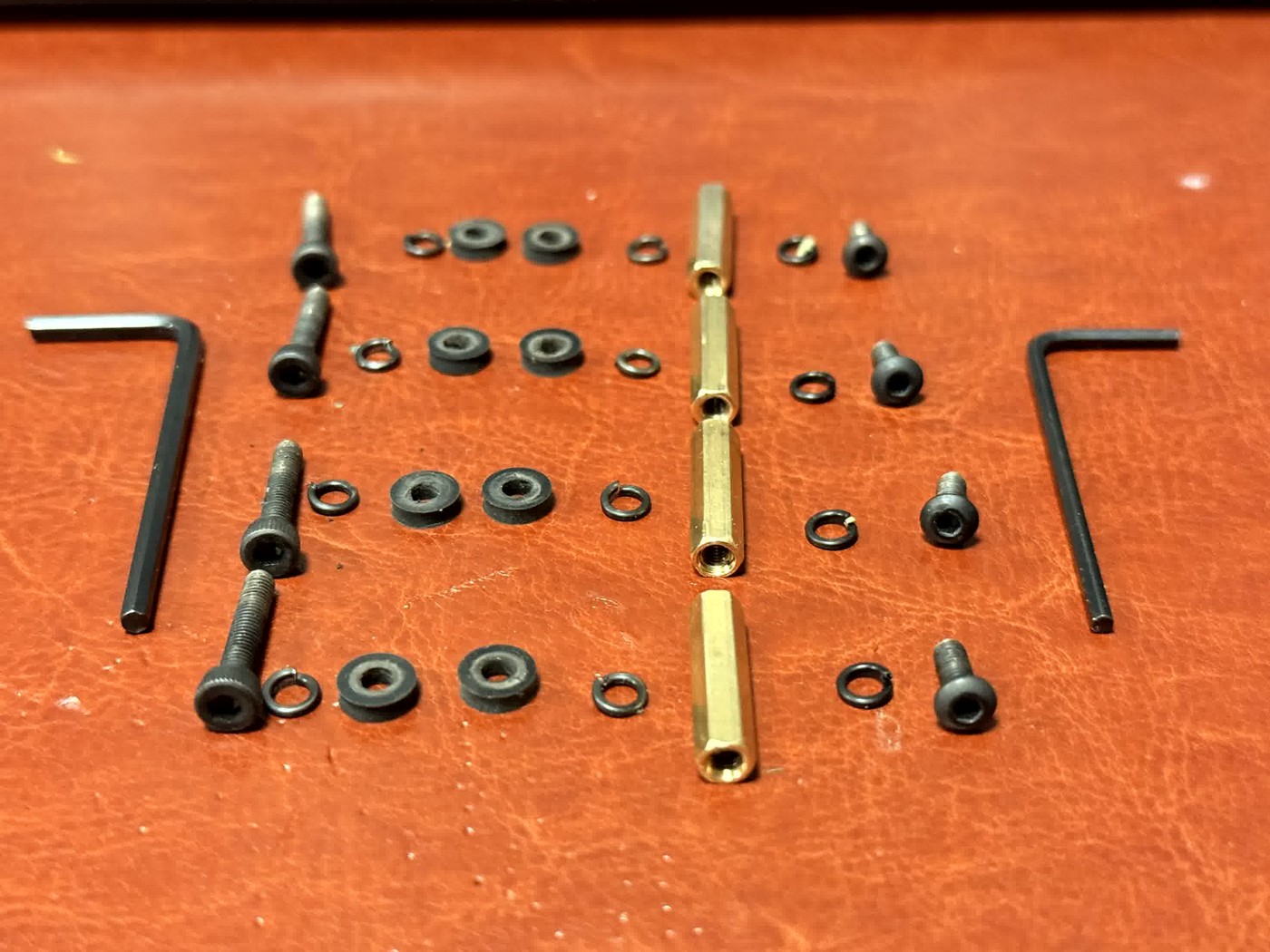
What's in the Box
This lists the components relevant to mounting only, the device, mounting dock, and hardware package. Your full shipment may include additional items such as sensor cables, solenoid wiring, and product-specific accessories covered in the installation guides.
Lay out all hardware before starting.
| Qty | Part | Description |
|---|---|---|
| 1 | Device | Water Buddi or Drip Defender device with foldable antenna, display, 4 LEDs, and mode button |
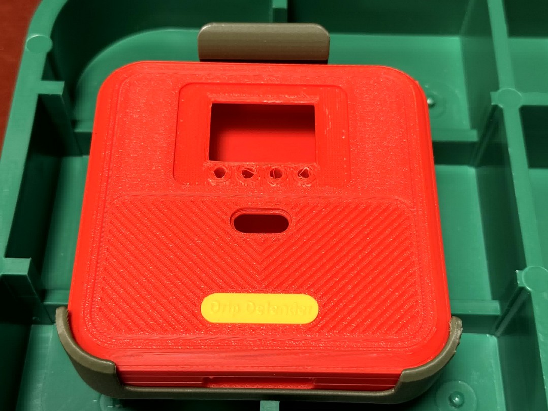
| 1 | Device Mounting Dock | Docking mount with corner clips and a latching tab with screw assembly for installing the knurled screw to secure the device into the dock |
| 4 | Brass Hex Standoff | M3 female-female, 20 mm length |
| 8 | Rubber Grommet | Flanged seal, one above and one below lid per hole |
| 4 | Long Cap Screw | M3 socket-head, ~25 mm, black oxide steel |
| 4 | Lock Washer | M3 split, black oxide steel |
| 4 | Short Cap Screw | M3 socket-head, ~8 mm, black oxide steel |
| 2 | Hex Key | 2.0 mm and 2.5 mm Allen wrenches |
| 1 | Drill Template | 110 lb cardstock, 4-hole pattern |
How It Goes Together
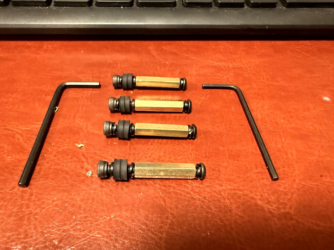
The device installs into the device mounting dock from the underside of the valve box lid on four brass standoffs. Each standoff passes through the lid on a sealed fastener stack. The device mounting dock is screwed into the standoffs with 4 screws and locking washers. The device then slides into the mounting dock and is secured with the knurled screw that is placed in the mounting dock release tab.
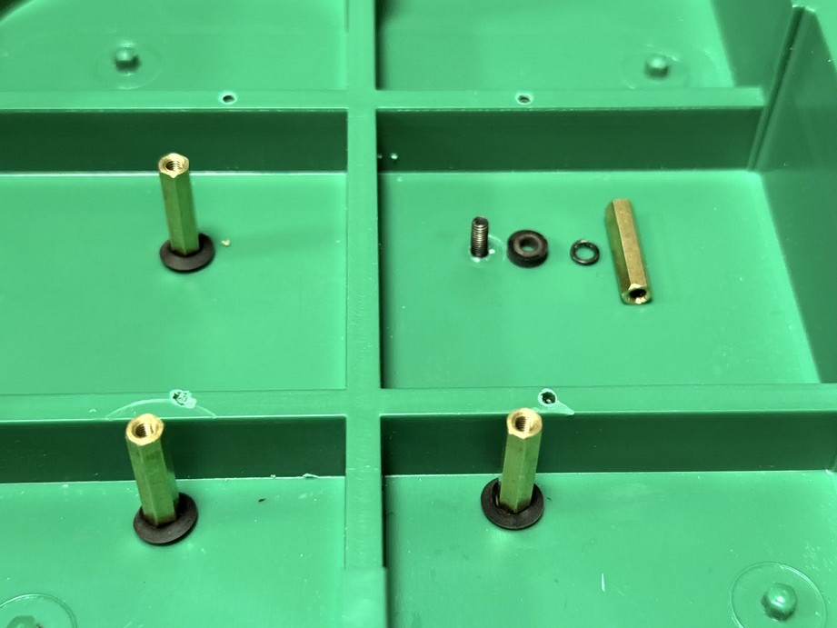
Before you drill: Each fastener stack uses two grommets, one above the lid, one below, with a lock washer seated between the screw head and the upper grommet. Together they sandwich the lid and seal each hole against rainwater. Do not skip either grommet or the lock washer.
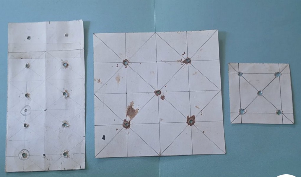
Step 1 - Drill the Lid
1. Mark and drill four holes in the valve box lid
Remove the valve box lid. Place the included paper drill template on the top (diamond plate side) of the lid. Use the corner clips of the lid to align the template, the four marked points should sit between the structural ribs. Mark each hole with a pencil through the template, then drill with a 1/8" bit straight through from the top.
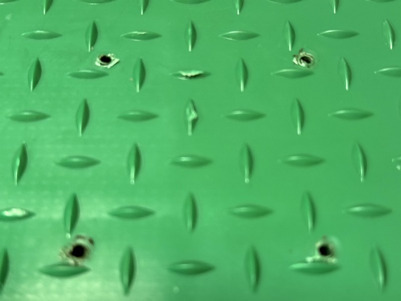
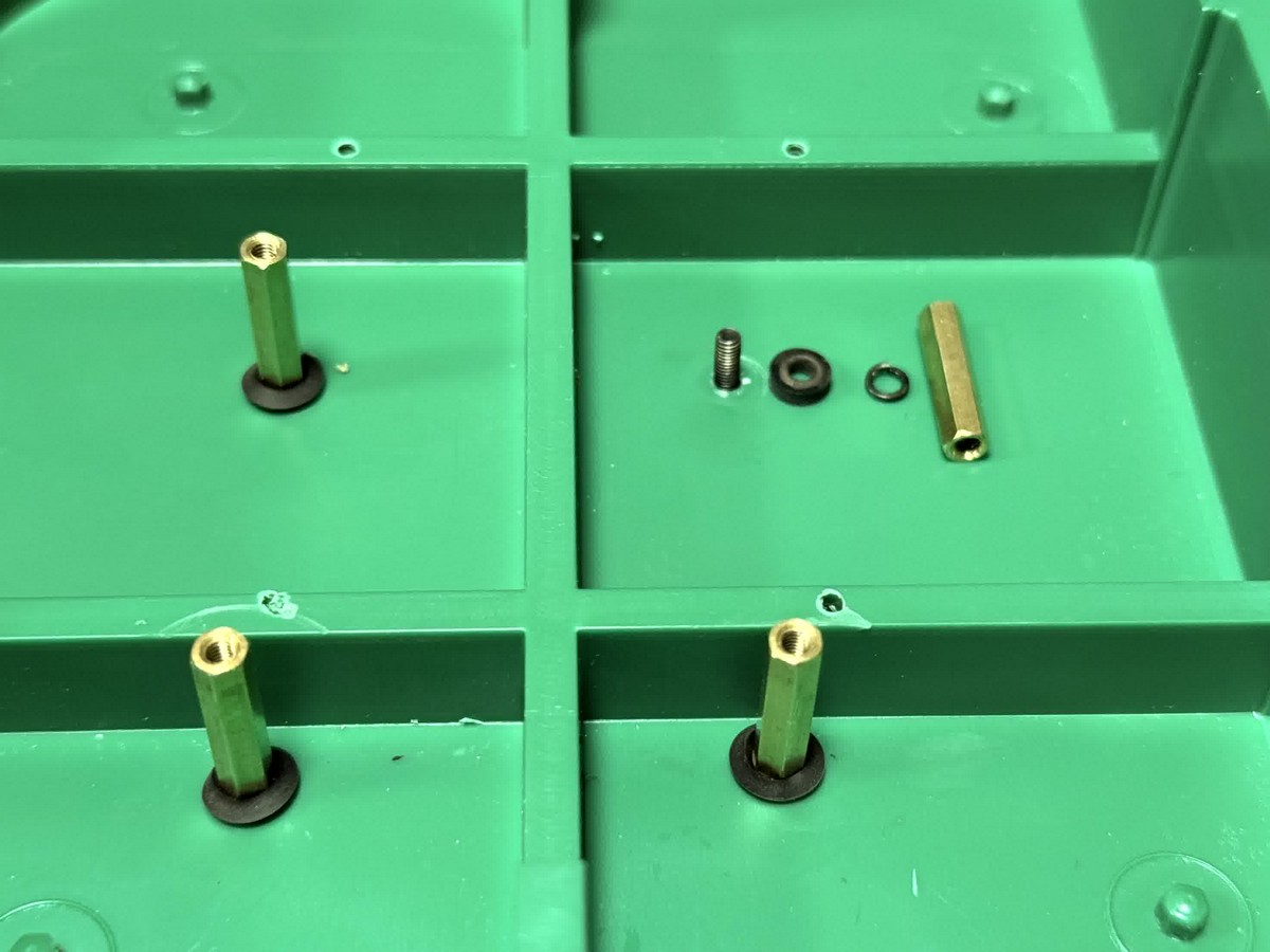
2. Seat the outer grommets on top of the lid
With the lid diamond plate facing up, insert a cap screw down through each hole with a lock washer seated directly under the screw head. From below, press a rubber grommet up onto the screw from the inside of the lid, then flip and press a second rubber grommet down from the top. The two grommets sandwich the lid, one on each face, sealing the hole against rainwater. The standoff then threads onto the screw from below, clamping the entire stack tight. Tighten snugly with the 2.0 mm hex key, do not overtighten or you will compress the grommets past their sealing point.
Step 2 - Build the Fastener Stacks
3. Assemble each fastener stack through the lid
With both grommets seated in each hole (outer on top, inner on bottom from step 2), drop a cap screw down through each stack from above with a lock washer already seated under the screw head. From below, thread the brass standoff onto the screw. Tighten snugly with the 2.0 mm hex key, do not overtighten.
Each stack from top to bottom:
- Long M3 cap screw (~25 mm)
- Lock washer (under screw head)
- Outer rubber grommet (top of lid)
- Lid
- Inner rubber grommet (underside of lid)
- Brass hex standoff (M3 F-F, 20 mm)
If the standoff spins while tightening, insert the 2.5 mm hex key into the female end of the standoff to hold it while driving the cap screw with the 2.0 mm hex key.
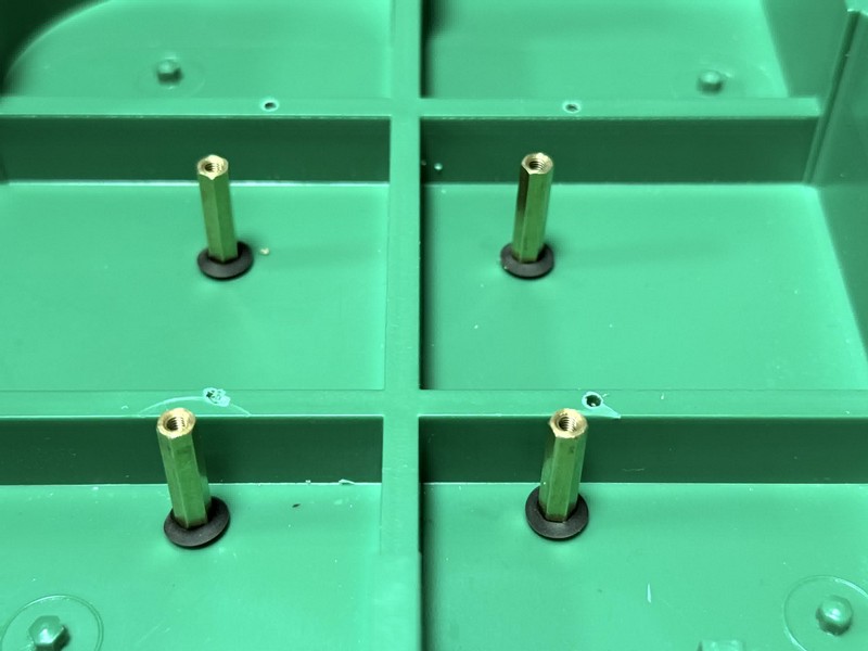
4. Repeat for all four corners
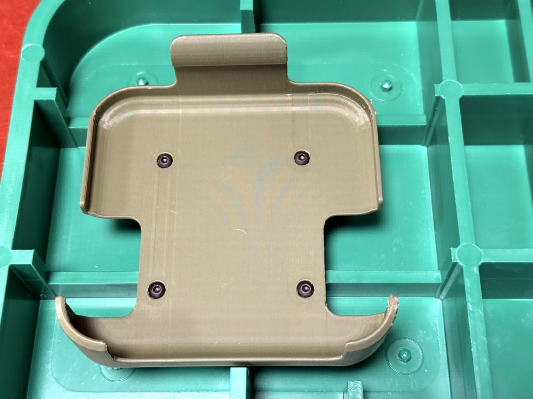
When finished, four brass standoffs hang from the underside of the lid with the female threads facing downward.
Step 3 - Attach the Mounting Dock and Device
5. Attach the device mounting dock to the standoffs
Hold the dock against the four standoff ends. Pass a short cap screw up through each of the four holes in the dock, place a lock washer on the screw between the dock and the standoff, then thread the screw into the standoff. From bottom to top on each standoff: short cap screw → lock washer → dock → standoff. Tighten snugly with the 2.0 mm hex key, do not overtighten.
6. Install the device into the mounting dock
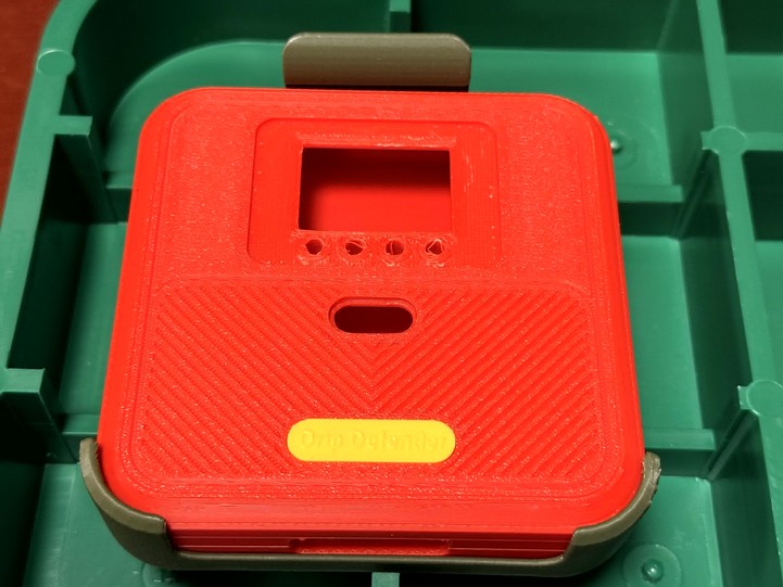
Slide the device into the mounting dock until it snaps into place. Thread the knurled screw into the latching tab to secure the device. Replace the lid; the device now hangs hidden inside the valve box.
To remove the device for servicing or rear wiring access, unscrew the knurled screw, press the release tab, and slide the device out of the dock.
Troubleshooting
Water leaking through the screw holes
Both grommets must be present and seated flat against the lid. Check that the screw is tight enough to compress the rubber but not so much that the grommet deforms or extrudes out the side.
Device won't seat in the cradle
Confirm device mounting dock orientation, the curved cradle goes opposite the brown catch slot. The device clips top-first, then rotates down into the cradle.
Standoff won't tighten and keeps spinning
Insert the 2.5 mm hex key into the female end of the standoff to hold it while tightening the long screw with the 2.0 mm hex key.
Device or dock becomes loose over time
Lock washers were likely missing or placed in the wrong position. Each standoff stack requires a lock washer seated directly under the cap screw head (between the screw and the outer grommet). Each dock screw requires a lock washer between the dock and the standoff. Re-read the assembly instructions and verify all lock washers are correctly positioned before re-tightening.
Hole pattern doesn't match my valve box
The included template fits standard 14" rectangular valve boxes. For non-standard boxes, mark four points in a square pattern with at least 3" spacing, avoiding internal lid ribs.
Need Help?
- In the app, from the hamburger menu select Management, then tap + in the Support card to start a new support session
- Web chat, available at telemetryinsights.com
- Email, support@telemetryinsights.com, My Buddi or a support specialist will respond